


Five-Petal Thumb-Loop Palm Vibrator
August 14, 2026
Five-Rib Concave-Waist Suction-Base Dildo
August 14, 2026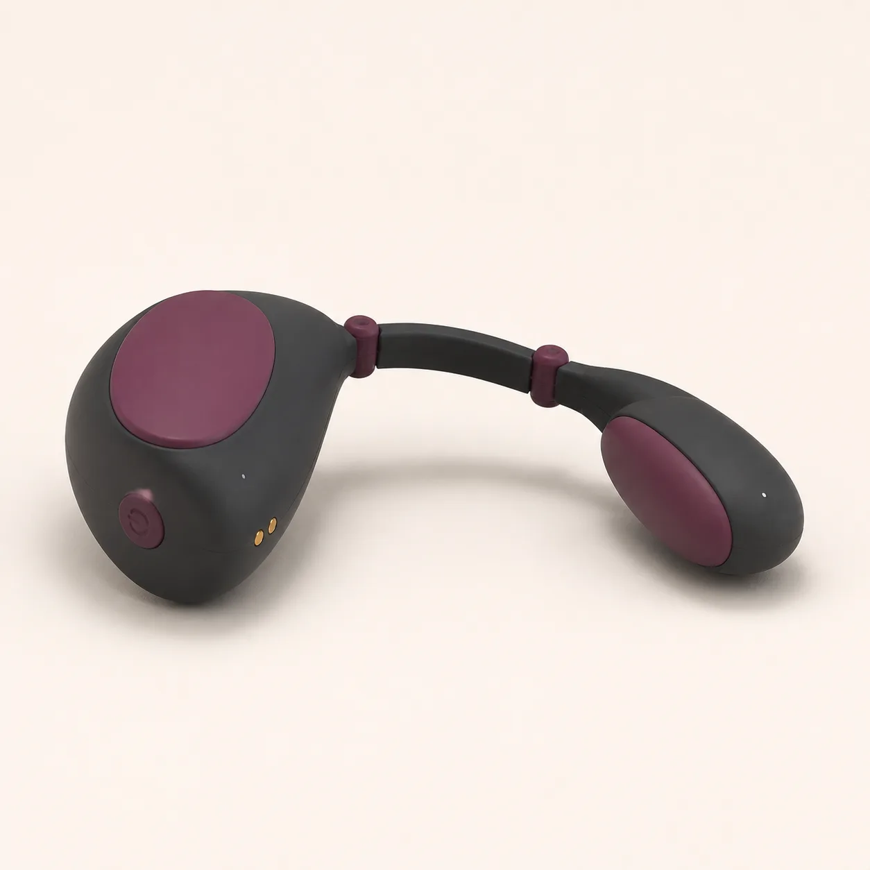
Three-Link Flex-Bridge Couples Vibrator with Offset Twin Contact Pods
A connected couples vibrator concept with two offset contact pods joined by a three-link bridge and two separately testable articulation joints.
39,99 $
200 in stock
Three bridge links separate reach from pod angle
This flex bridge couples vibrator concept joins two offset contact pods with three short links and two low-profile hinge collars. The structure is intended for measurable adjustment of spacing and contact-face angle without assuming that either pod fits a specific body position.

The image does not prove hinge range, detents, motor count, independent output, wearable stability, material, waterproofing, runtime or safe fit.
Inventory the bridge, pods and hidden signal path
Request drawings and a bill of materials for both pod shells, contact pads, three bridge links, two hinge pins or flex joints, collars, stops, wiring, strain reliefs, actuators, controller, battery, button, indicators, charging contacts, pigments, seals, lubricants and adhesives.
Confirm where conductors cross each joint and whether pod motion can pinch or fatigue them.
Measure the neutral arch before testing articulation
Record pod length, width and depth, pad area, bridge-link length and thickness, hinge spacing, neutral pod-to-pod distance, face offset, overall mass, control reach and contact locations.
Measure from fixed datum points on both shells so hinge movement can be compared across samples.
Map the first hinge through its verified travel
Support the bridge links and move only the hinge nearest the larger pod through small documented increments. Record angle, torque, free play, any detents, stop contact, rebound and conductor strain indications.
Reject rough travel, collar lift, sudden jumps or a stop that exposes a hard edge.
Map the second hinge independently
Repeat the same measurements at the joint nearest the smaller pod while the first hinge remains at a reference angle. Compare clockwise and counterclockwise torque and position holding.
Two visually similar collars may carry different loads because the pods have different mass and orientation.
Build a two-hinge position matrix
Combine only verified hinge positions and log pod spacing, face angle, bridge clearance, stored spring force and stability on a non-body fixture. Include mirrored and asymmetric settings.
Exclude combinations that self-fold, overtwist the bridge, make shells collide or cover controls and contacts.
Characterize the larger pod on its own
Measure vibration amplitude, frequency, startup, decay, sound, current and surface temperature on the larger contact pad and surrounding shell at each confirmed program and charge level.
Document whether the indicator reports power, program, charge or a different state.
Characterize the smaller offset pod separately
Repeat the output and thermal measurements at the smaller pod. If it lacks an actuator, quantify vibration transferred through the bridge instead of describing it as independently powered.
Compare contact-pad and shell readings so useful output is not confused with structural buzz.
Measure cross-pod coupling through both hinges
Use synchronized sensors on both pods and all three links while programs run at several hinge combinations. Record phase, amplitude transfer, resonance, sound and changes when one pod contacts a compliant test surface.
A bridge can amplify or attenuate output as angle changes, so free-air results are incomplete.
Evaluate contact pressure on a guarded fixture
Place both pads against separate compliant instrumented surfaces within supplier limits. Measure force distribution, slip, pod rotation, bridge lift and control access at selected hinge settings.
No generic fit claim should replace documented pressure maps and clear size limitations.
Audit the single control and charging contacts
Confirm button functions, press duration, lockout, program order, memory, indicator meanings, low-battery behavior, contact polarity, cable specification, charger input, charge time, runtime and operation during charging.
A single button does not establish synchronized or independent pod control.
Track current, heat and shutdown in loaded positions
Run the highest verified program with both pods on approved compliant fixtures at several allowable bridge positions. Log battery current and temperatures at pads, shells, joints, links, controller, battery and charging contacts.
Verify shutdown and restart behavior if one pod is obstructed on a guarded test rig below confirmed limits.
Cycle hinges and vibration as one assembly
Run repeated articulation sequences interleaved with vibration and compliant-load checks. At planned intervals inspect collars, pins, link surfaces, wire paths, strain reliefs, pad bonds, seams, button and contacts.
Track torque drift, free play, output balance, noise, heat, cracks, whitening and intermittent electrical behavior.
Verify materials and clean every moving junction
Obtain exact formulations for pads, pod shells, bridge links, collars, internal supports, wire jackets, seals, coatings, pigments, lubricants and adhesives plus restricted-substance, skin-contact, electrical and battery evidence.
Use only the verified cleaning method. Inspect and dry around pad edges, pod seams, both hinge collars, link gaps, button, indicators and charging contacts. Immersion, boiling, alcohol, bleach, abrasives and oils require explicit compatibility evidence.
Price the articulated assembly after load testing
An Alibaba U-shaped couples vibrator listing currently shows USD 2.50-5.20 with an MOQ of three pieces. It is a category benchmark only and does not confirm this three-link bridge, offset twin pods or an approved supplier.
The procurement reference supports an EUR 39.99 planning price after allowing for China-origin freight, exact-part inventory, two-hinge mapping, position matrix, separate pod output tests, cross-pod coupling, compliant pressure maps, loaded current and heat, joint cycle life, materials and battery documentation, cleaning validation, protective packing and discreet fulfillment. Exact quotation, MOQ, packed dimensions, weight, freight, duty, tax, insurance, payment fees and delivery terms remain pending.
Frequently asked questions
Do both contact pods contain motors?
That remains unconfirmed; each production pod and the vibration transfer through the bridge require measurement.
Can the two hinges hold any angle?
Only stable positions within documented travel and stop limits should be used; appearance does not prove continuous adjustment.
Does the device synchronize with a phone?
No app or wireless control is represented or confirmed for this concept.
Can it be worn during movement?
Wearable stability, pressure and permitted activity require exact-model fit instructions and controlled sample testing.
May it operate while charging?
Only if confirmed instructions explicitly permit it; otherwise keep the device off and dry during charging.
Which faults require retirement?
A cracked link, loose collar, exposed pin or wire, unstable hinge, lifted pad, split seam, failed control, intermittent pod, unusual heat, battery swelling or corrosion.
Reviews
There are no reviews yet.