


Four-Cuff Under-Mattress X-Web Restraint with Independent Pull-Tab Releases
August 14, 2026
Four-Cuff Twin-Rail Indexed Spreader Restraint
August 14, 2026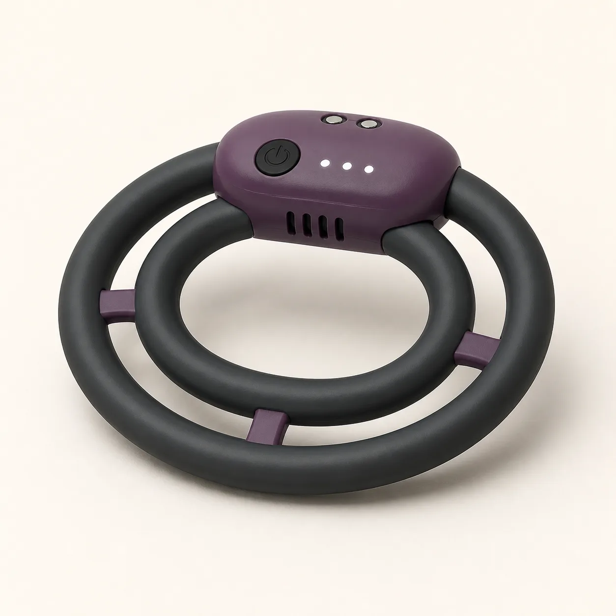
Twin-Layer Three-Bridge Couples Ring
A rechargeable couples ring concept with two concentric flexible loops, three load-balancing bridges and one shared vibration pod.
64,99 $
200 in stock
Balance two nested loops through three bridges
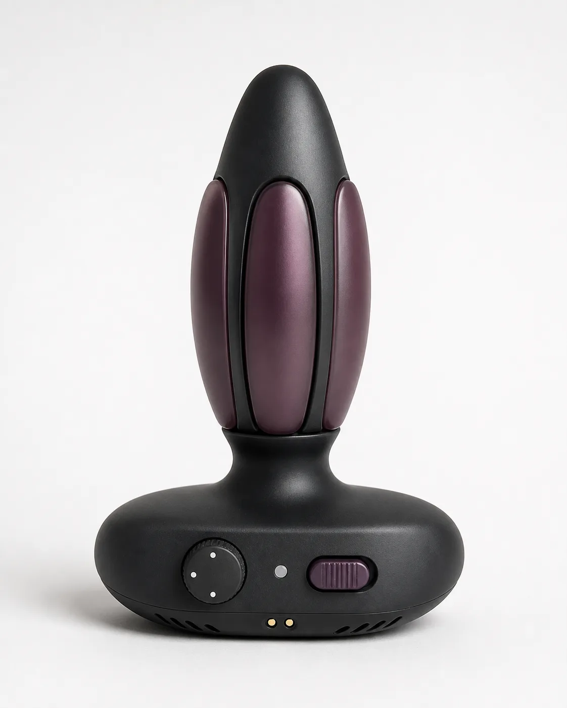
This twin-layer three-bridge couples ring concept places one flexible charcoal loop inside a larger matching loop. Exactly three smoky-plum bridges maintain the gap, while one vibration pod spans both layers with a power control, three indicators, four vents and two charging contacts.

The image establishes a test architecture and does not confirm fit, bridge action, output, materials, battery or production status.
Identify the complete load and electrical path
Label inner loop L1; outer loop L2; bridges G1-G3; pod P0; control B0; indicators I1-I3; vents V1-V4; contacts J1-J2; motor, controller, cell, seals, pigments, adhesives, molded joints and fasteners.
Require exact-sample drawings and firmware identity before assigning function to visible parts.
Measure both loop geometries
Record relaxed inner dimensions, cross-section, circumference, hardness, mass and ovality for L1 and L2. Measure their separation at fixed angular stations.
Reject thin zones, abrupt section changes, exposed hard parts, cracks, tack or uncontrolled loop contact.
Characterize bridge G1 through G3
Measure length, width, thickness, angle, hardness, edge blend and attachment footprint for every bridge. Record deflection under radial, tangential and torsional fixture loads.
Three visible bridges are not equally loaded until strain and displacement data confirm distribution.
Map differential stretch between layers
Expand L1 and L2 individually and together across bounded fixture diameters. Log force, elongation, bridge rotation, pod movement and recovery after dwell.
Separate intended compliance from bridge peel, local necking and permanent set.
Verify three proposed intensity indicators
Map B0 and I1-I3 to startup, program, intensity, pause, immediate stop, travel lock and low-battery response. Record acceleration, frequency, current and temperature at every confirmed state.
Three dots remain reference marks until electrical and mechanical measurements identify distinct settings.
Build spatial output maps
Measure acceleration, frequency and harmonics across P0, both pod edges, L1, L2, G1-G3 and points opposite the pod. Compare unloaded and bounded-stretch states.
Plot transfer into each loop rather than relying on a single peak value at the motor housing.
Repeat mapping under asymmetric preload
Use calibrated compliant fixtures to load one loop, both loops and individual bridge sectors. Log output, contact force, bridge strain, pod tilt, current and heat.
Reject abrupt pressure concentration, bridge inversion, pod edge contact or unstable programs.
Inspect gaps joints and pinch guards
Gauge the space between L1 and L2 through all verified stretches and twists. Probe bridge roots, pod sockets, seams and controls for pinch, snag, abrasion and exposed hard transitions.
Reject closing gaps that capture probe material or allow the loops to cross unexpectedly.
Assess control access and stop priority
Measure B0 actuation force and access under dry, damp and gloved fixture handling. Time the shortest action from every confirmed program to full drive stop.
Immediate stop must not require cycling through intensity or pattern states.
Validate charging and battery protection
Confirm J1-J2 polarity, input limits, charge time, operating time, cutoff, standby drain, partial-contact behavior and contact temperature. Test interrupted charging and repeated discharge.
Battery chemistry, capacity, cable specification and transport documents remain pending supplier evidence.
Trace vents sound and heat
Map air paths through V1-V4 and measure A-weighted sound plus temperatures at the motor, controller, cell, pod surfaces, bridge roots, loops, vents and contacts.
Distinguish normal output from housing buzz, blocked airflow, loose fasteners and motor wear.
Design cleaning and drying challenges
Apply visible test soil to both loops, bridge roots, inter-layer gap, pod seams, control, vents and contacts. Record residue, cleaning access, drying time, swelling, corrosion and post-cleaning tack.
No waterproof or immersion claim is made without exact-model ingress documentation and testing.
Confirm materials and cyclic durability
Request declarations for both loops, bridges, pod shell, control, pigments, adhesives and seals. Cycle stretch, twist, programs, charging, cleaning and storage, then remeasure loop geometry, bridge strain, output, sound and heat.
Retire samples for cracks, bridge peel, permanent stretch, abnormal heat, fluid entry, charging faults or cell swelling.
Build landed price after twin-layer validation
An Alibaba wearable-vibrator category page showed one example starting at USD 7.99 with a one-piece minimum. It is a broad benchmark only and does not identify this twin-layer ring or an approved supplier.
The public procurement benchmark supports an EUR 64.99 planning price after provisional allowance for China-origin freight, exact samples, loop and bridge metrology, differential stretch, spatial and loaded output maps, controls, sound, heat, charging, cleaning, fault and fatigue work, protective packing and discreet fulfilment. Exact supplier, quote, MOQ, dimensions, materials, battery, packed weight, freight, duty, tax, certification, payment terms and lead time remain pending.
Frequently asked questions
How many loops are shown?
The concept uses exactly two separate concentric flexible loops.
What do the three bridges do?
They propose controlled spacing and load sharing, which require strain testing.
Are three intensity levels confirmed?
No. The three indicators require measured output, current and heat data.
Can both loops stretch independently?
Differential and combined stretch behavior must be measured on bounded fixtures.
Is the ring waterproof?
No ingress rating is claimed for seams, vents, control or charging contacts.
Which faults require retirement?
Cracks, bridge peel, permanent stretch, heat, fluid entry or cell swelling.

Reviews
There are no reviews yet.