


Zippered Care-Surface Pillow Protectors, 2-Pack
August 14, 2026
Pressure-Responsive Flat-Head Wand with Segmented Grip Strip
August 14, 2026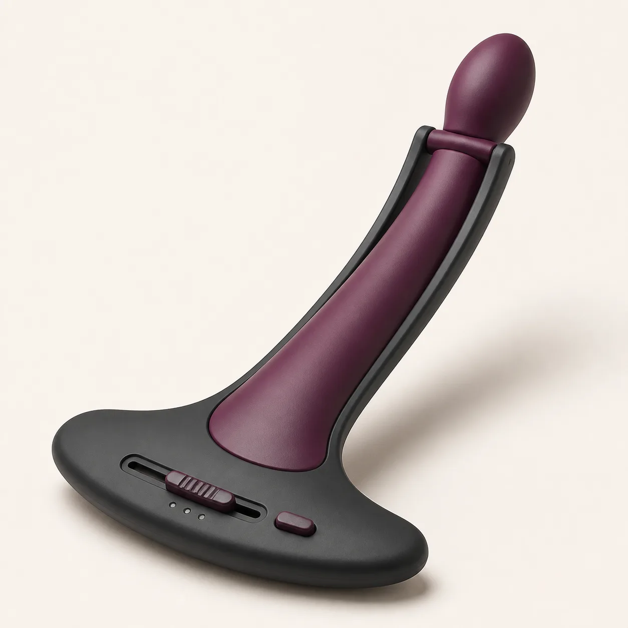
Three-Stop Lateral-Bias Prostate Trainer with Twin Cantilever Rails
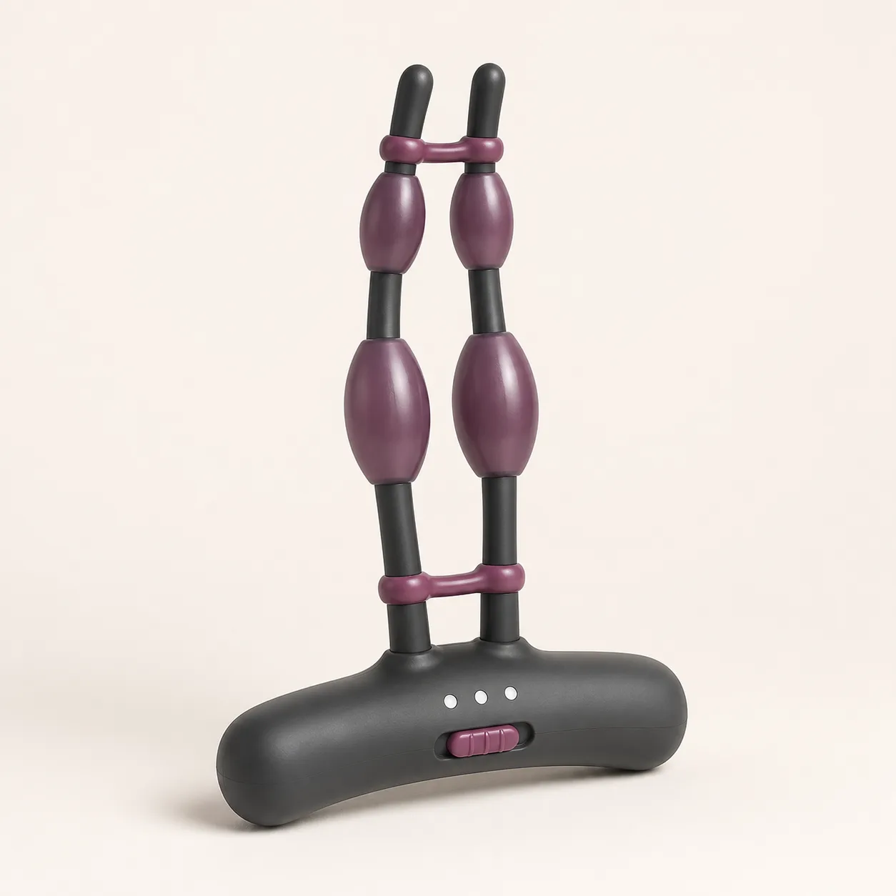
A manual prostate trainer concept with twin external cantilever rails and a three-position base slider proposed to bias the rounded head laterally.
31,99 $
200 in stock
Shift the head laterally without changing shaft depth
This lateral bias prostate trainer concept uses two external cantilever rails and a transverse bridge beneath one rounded asymmetric head. A guarded three-stop slider in the oversized crescent base is proposed to bias the rails left, center or right while preserving the main curved shaft profile.

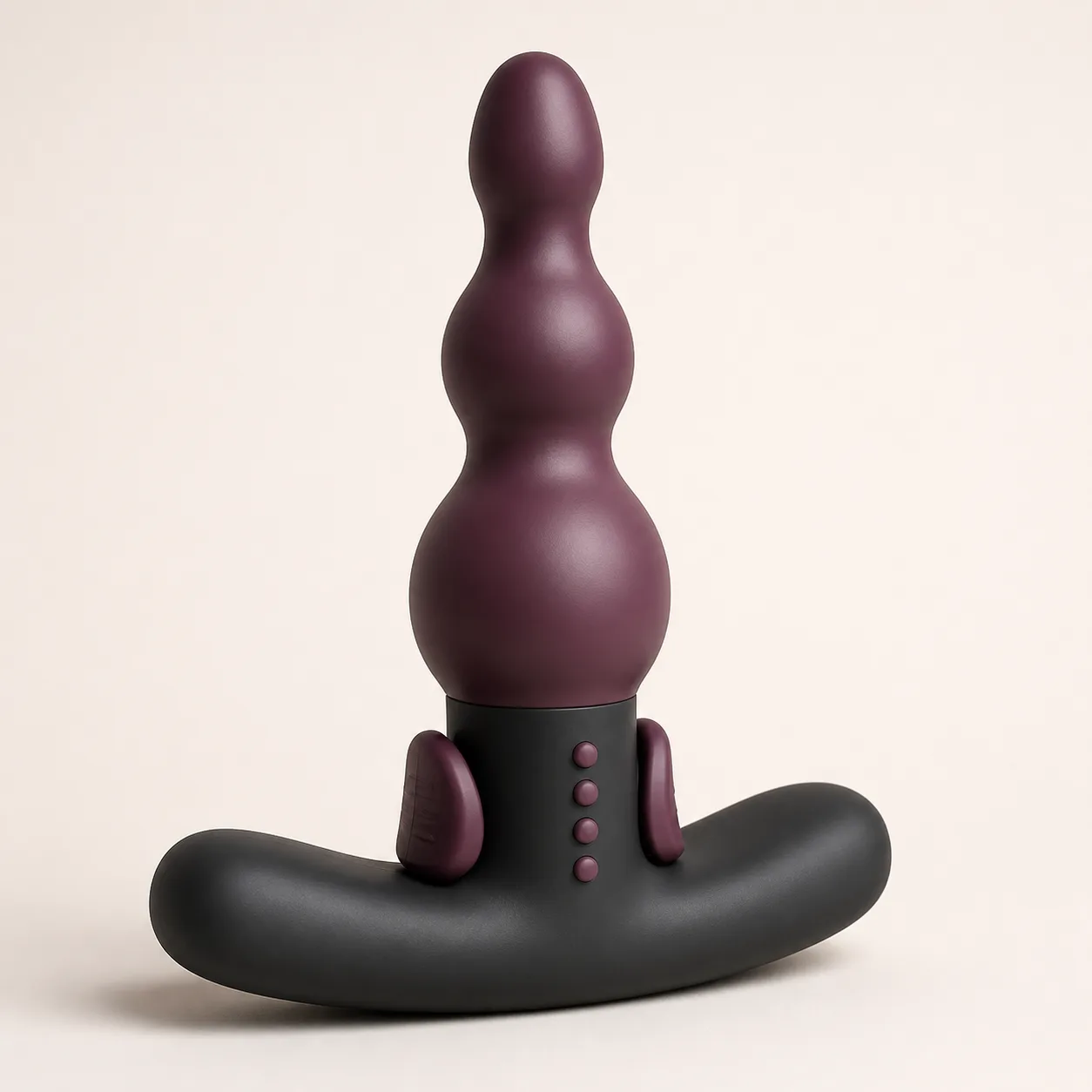
The image does not prove lateral travel, rail stiffness, load, pressure, fit, dimensions, material composition or production availability.
Inventory the complete bias mechanism
Request an exploded drawing and bill of materials for the head, shaft, transverse bridge, left and right rails, base frame, slider, carriage, linkages, detents, lock tab, stops, bushings, fasteners, pigments, coatings, lubricants and adhesives.
Trace the load path from the base slider to each rail and identify whether one carriage pulls both rails or separate linkages create the offset.
Establish the center-position geometry
At the verified center stop, record total length, insertable length, shaft profile, head length, width and offset, bridge width, neck width, rail spacing, base span, base thickness, slider projection and mass.
Use a coordinate fixture to record the head center relative to the base and curved shaft rather than relying on visual alignment.
Verify the oversized external base
Measure crescent span, corner radius, bending stiffness, neck-junction strength, contact footprint and resistance to folding through representative fixtures. Confirm the base stays visibly and mechanically external in every approved orientation.
Head adjustment cannot compensate for an inadequate external stop; retire any sample whose base curls, cracks or narrows under load.
Calibrate slider and lock states
Measure track coordinate, travel, detent force, tactile confirmation, lateral play and accidental movement resistance for left, center and right. Approach each stop from both directions to expose backlash.
Test the separate lock tab for engagement depth, actuation force, false seating and movement while locked.
Measure each rail independently
Track lateral and axial rail displacement, bending stiffness, torsion, symmetry and spring-back under controlled slider movement and standardized head loads. Inspect attachment points at the bridge and base.
Stop for rail lift, buckling, cracking, asymmetric permanent set, rubbing against the shaft or an exposed hard edge.
Map the head position in three dimensions
Record head-center coordinates, yaw, pitch, roll and profile at every slider stop under unloaded and compliant-loaded conditions. Repeat across temperature and after conditioning.
A nominal left or right position may also change head angle, insertion profile or local shaft curvature.
Measure force and pressure by bias setting
Use an instrumented compliant fixture to record lateral force, axial force and contact pressure at the head, bridge, shaft and rail-adjacent regions. Apply small controlled displacements in all three positions.
Define conservative limits from peak local pressure and highest rail stress rather than the average force at the base slider.
Confirm a repeatable neutral state
Develop a fixture check for the center detent, head-center coordinate, rail symmetry and lock status before insertion and before removal. Repeat after every load sequence.
Do not assume the middle visual dot equals mechanical neutral if backlash, rail drift or a partly engaged lock is present.
Measure movement and retention separately
Move the complete trainer along a standardized compliant path at controlled speed while holding each verified bias setting. Record entry, sustained and extraction resistance, stick-slip, base rotation, slider creep and rail contact.
Test external-base retention independently under axial, lateral and torsional loads using fixtures only.
Inspect bridge, rails and track for pinch zones
Use feeler gauges and articulated fixtures to inspect the transverse bridge ends, rail-to-shaft gaps, rail anchors, slider track, lock recess, base corners and neck junction throughout adjustment and loading.
Reject accessible gaps that close sharply, raised rail edges, protruding fasteners, track burrs or a slider that can trap skin.
Validate materials and surface compatibility
Obtain exact composition and restricted-substance evidence for every contact surface, coating, pigment, lubricant and adhesive. Do not infer material from appearance or texture.
Condition samples with only documented compatible lubricants and cleaners, then measure swelling, tack, whitening, cracking, rail stiffness, bond strength, slider friction and color transfer.
Cycle bias, loading and neutralization
Run repeated center confirmation, left bias, lock, compliant loading, unlock, center, right bias, lock, extraction, cleaning, drying and storage cycles. At checkpoints repeat geometry, rail stiffness, head coordinates, pressure, detent, lock and base-retention tests.
Retire after rail drift, lost center, false lock, slider creep, bridge damage, cracked shaft, weakened base, exposed edge or incompatible surface change.
Clean around rails without trapping residue
Use the exact approved cleaning method for the confirmed materials. Inspect the head, bridge underside, both rail faces, rail-to-shaft gaps, anchor points, slider track, lock recess, neck and base perimeter.
Measure drying by mass and verify the slider moves cleanly only after all gaps are dry. Immersion remains unapproved without exact evidence.
Price after lateral displacement is proven
An Alibaba manual prostate-exerciser listing currently shows a curved category example at USD 1.48 with MOQ twenty. It is a category benchmark only and does not confirm this twin-rail lateral-bias mechanism, three-stop slider or independent lock.
The procurement reference supports an EUR 31.99 planning price after allowing for China-origin freight, exact-model sourcing, teardown, center-position metrology, base-retention tests, slider and lock calibration, per-rail stiffness, three-dimensional head maps, force and pressure analysis, movement resistance, pinch inspection, cycle life, material evidence, cleaning validation, protective packing and discreet fulfillment. Exact quotation, packed size, weight, freight, duty, tax, insurance, payment fees and delivery terms remain pending.
Frequently asked questions
Does the slider change insertion depth?
The concept targets lateral head bias; actual axial movement and profile changes must be measured.
Are left and right positions symmetrical?
No symmetry is claimed until rail displacement, head coordinates and force are compared under load.
Can the setting change while loaded?
The approved adjustment sequence remains pending; unintended slider movement or a false lock is a retirement fault.
How is center confirmed?
Use a verified detent, lock state, head coordinate and rail-symmetry check rather than the visual dot alone.
Can it be immersed?
No ingress claim is made; rail gaps, anchors, the slider track and lock recess require documented cleaning.
Which faults require retirement?
Rail drift, lost center, false lock, slider creep, bridge damage, cracked shaft, weakened base or an exposed edge.
Reviews
There are no reviews yet.