



Four-Window Sliding-Damper Bullet Vibrator with Three-Stop Sleeve
August 14, 2026
Four-Shutter Three-Aperture Palm Vibrator
August 14, 2026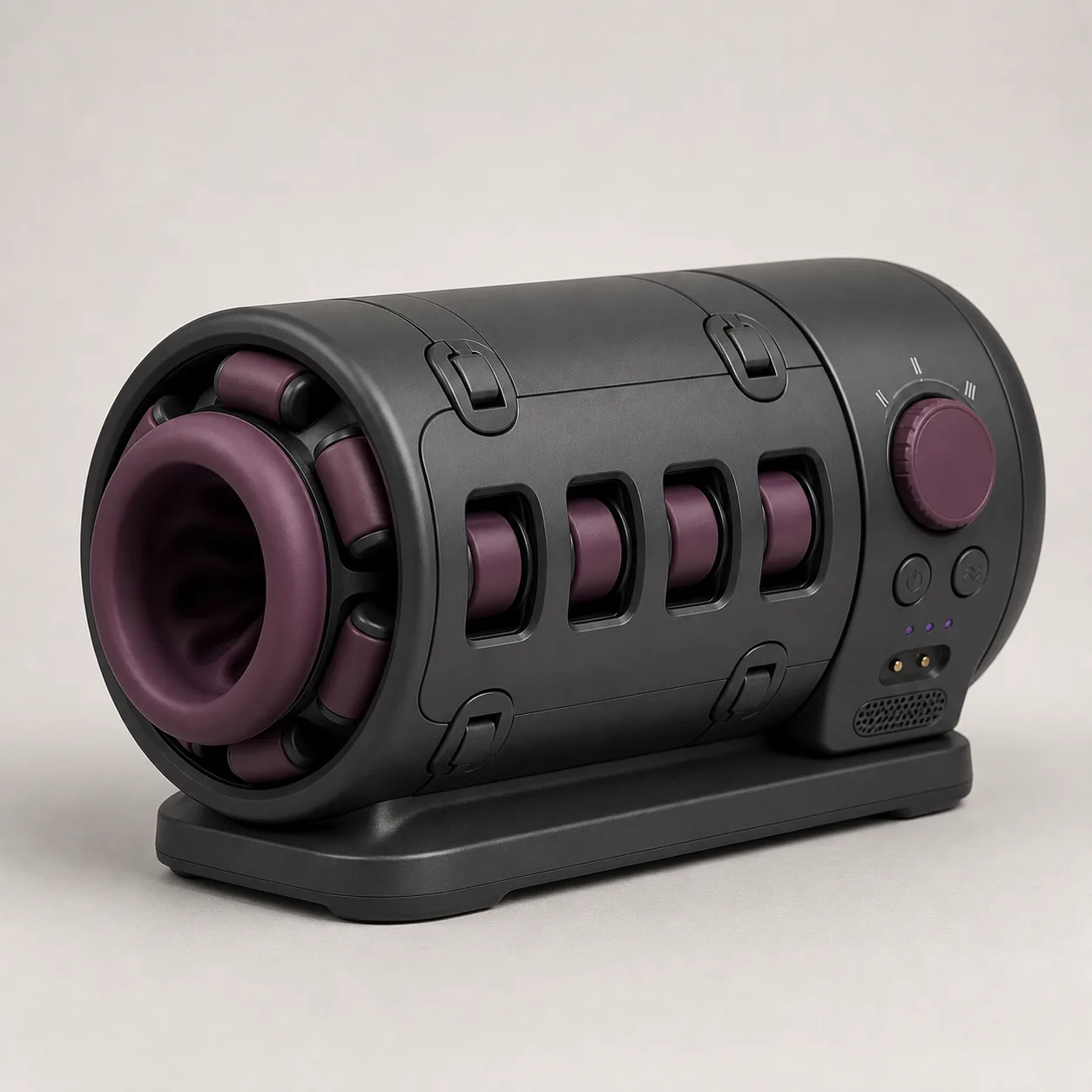
Six-Roller Planetary-Cage Automatic Stroker with Split Service Shell
A bench-style automatic stroker concept with six planetary rollers around a removable liner, a split service shell, captive latches and three-index drive dial.
79,99 $
200 in stock
Drive one removable liner with a six-roller cage
This six-roller planetary-cage automatic stroker concept places six rounded plum rollers around an abstract removable liner. A charcoal cage supports the rollers inside a split service shell, while a rear motor housing, three-index dial and stable base create a bench-style automatic format.

The image does not prove roller count, planetary motion, liner fit, pressure, stroke, dimensions, materials, electrical safety, sealing, cleaning access or production availability.
Inventory the complete drive and liner system
Request an exploded bill of materials for the removable liner, entrance collar, six rollers R1 through R6, axles, bushings, planetary cage, ring gear or carrier, guides, split shell halves, four captive latches, rear drive, reduction stage, three-index dial, buttons, indicators, board, cell, contacts, vent, base, seals, fasteners, pigments, lubricants and adhesives.
Trace each component to drawings, tolerances, batch records and the approved sample.
Establish machine and passage dimensions
Measure overall length, width and height, base footprint, liner entrance axes, internal passage length, roller-circle diameter, roller spacing, cage position, shell-wall thickness, drive housing, control clearances, mass and center of gravity. Record level and tilt on the base.
Dimensions must be confirmed with the liner installed, removed and conditioned.
Characterize the removable liner independently
Measure relaxed and supported passage geometry, wall thickness, entrance radius, texture, hardness, compression recovery, tear resistance, mass and attachment features. Inspect seams, voids, thin regions, hard inclusions, odor, color transfer and cleaner compatibility.
Verify that removal and installation cannot fold the wall into a hidden pressure ridge.
Measure rollers R1 through R6
For every roller, record diameter, length, crown, surface finish, hardness, runout, radial play, axial play, breakaway torque, loaded rolling torque and retainer overlap. Compare all six values rather than relying on a set average.
Quarantine rollers with flat spots, wobble, rough bearings, lifted guards or exposed axle ends.
Prove the planetary cage trajectory
Use encoder data and high-speed imaging to map carrier angle, individual roller rotation, orbit radius, phase spacing and speed through a complete cycle. Confirm whether each roller both orbits and spins or follows another defined path.
The mechanism description must match measured motion and must not be inferred from the shell windows.
Map circumferential liner loading
Fit an instrumented compliant mandrel inside the liner and record pressure, tangential force, slip and roller passage at multiple diameters and dial positions. Compare six angular sectors and forward versus reverse operation if both directions are supported.
Watch for one overloaded roller, liner bunching, cage eccentricity or an abrupt entrance load.
Verify the split service shell
Open both shell halves using the documented sequence and inspect hinge or guide alignment, edge coverage, captive hardware, wiring protection, roller access and liner clearance. Measure reassembly repeatability and cage concentricity after repeated service.
Consumer access must not expose energized parts, sharp gear teeth or detachable roller retainers.
Test all four captive latches
Measure latch travel, engagement depth, operating force, false closure and retention under conservative vibration and shell-separation fixtures. Confirm that each latch remains captive when open and cannot be installed in a partial state.
Interlock behavior, if present, must prevent powered motion with an unsecured shell.
Calibrate the three-index speed dial
Record dial angle, detent torque, hysteresis, command value and actual cage speed at all three marks. Approach each stop from both directions and repeat under representative liner load and low-cell conditions.
An intermediate dial position must not cause unstable speed, chatter or unexpected direction change.
Measure stroke rotation current and torque
Log cage speed, any axial travel, roller rotation, motor current, drive torque and cycle timing with controlled preload. Test startup, steady operation, stall protection and shutdown separately.
Claims of thrusting, rotation or suction remain pending unless each motion is directly measured.
Verify controls charging and interlocks
Identify button functions, indicator patterns, charging polarity, specified lead, charger limits, cell protection, low-voltage response, lid or latch interlocks and power-loss behavior. Interrupt power at each dial stop and verify a predictable off state.
No restart should occur solely because power or a shell panel is restored.
Measure sound heat stability and base movement
At each speed and load, log A-weighted sound, shell vibration, base displacement, accessible temperature and hot spots at the motor, bearings, cage guides, contacts and vent. Repeat after a conservative blocked-roller simulation.
Investigate creeping, rocking, rising current, gearbox noise, hot latches or intermittent indicators.
Challenge one seized roller and cycle cleaning
Immobilize one protected roller in a fault specimen while tracking cage load, neighboring rollers, liner pressure, current, heat, sound and shutdown. Stop before damage and quarantine any machine with axle migration, guard contact or torn liner.
Run repeated operation, dial changes, safe stops, shell opening, liner removal, cleaning, measured drying, reassembly, charging and storage. Recheck dimensions, roller play, cage trajectory, pressure, latches, interlocks, electrical condition and residue paths.
Build landed price after drive proof
An Alibaba automatic-stroker page currently shows a motorized suction-category example at USD 30.00-42.00 with MOQ one. It is a benchmark only and does not confirm this six-roller cage, split service shell, removable liner or an approved supplier.
The procurement reference supports an EUR 79.99 planning price after allowing for China-origin freight, exact-model sourcing, liner inspection, six-roller metrology, cage trajectory and pressure mapping, shell and latch checks, dial calibration, electrical and interlock review, sound and heat measurement, fault and cycle testing, protective packing and discreet fulfillment. Exact quotation, MOQ, materials, battery, packed size, weight, freight, duty, tax, insurance, payment fees, certifications and delivery terms remain pending.
Frequently asked questions
Do all six rollers move independently?
Individual spin and planetary orbit must be measured for R1 through R6 under the same controlled load.
Is the liner removable?
The concept shows a removable liner, but attachment, reinstallation and cleaning instructions require sample proof.
Can the shell open while powered?
An interlock should prevent motion with an unsecured panel; its presence and response remain pending.
Does the dial control three speeds?
Each mark must be calibrated against command value, cage speed, current and load stability.
Is the device waterproof?
No sealing claim is confirmed; the split shell, controls, contacts, vent and liner interface need evidence.
Which faults require retirement?
Seized or loose rollers, axle migration, cage contact, torn liner, false latching, failed interlock, exposed wiring, abnormal heat, swelling or persistent residue.
Reviews
There are no reviews yet.