



App and Remote Wearable Massager – Compact Magenta Design
August 14, 2026
Dual-Module Magnetic-Link Couples Vibrator Set
August 14, 2026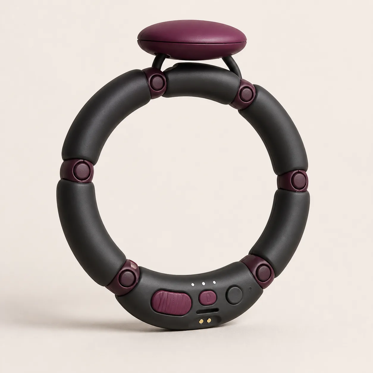
Six-Link Parallel-Motion Couples Ring with Floating External Pod
An adjustable couples ring concept with six guarded arc links, a lower slider bridge, quick release and a floating external vibration pod.
47,99 $
200 in stock
Change one circular opening through six linked arcs
This six-link parallel-motion couples ring concept uses six rounded charcoal arc links connected by guarded plum pivots. A lower control bridge coordinates the visible linkage, while a low-profile external pod rides above the ring on two support beams instead of being molded into one rigid circumference.

The image does not prove usable opening range, synchronized travel, joint guards, pod output, dimensions, material composition, body fit, cleanability, electrical sealing or production availability.
Inventory the linkage pod and control bridge
Request an exploded bill of materials covering arc links L1 through L6, pivot pins P1 through P6, bushings, end stops, guard caps, the lower bridge, slider, quick-release tab, indicator windows, buttons, pod shell, two support beams, motor, eccentric mass, cell, board, charging contacts, vent membrane, seals, fasteners, pigments, lubricants and adhesives.
Trace every part to drawings, batch records and the approved sample; a generic ring specification is not adequate evidence for this articulated assembly.
Measure relaxed geometry before actuation
Record inner opening axes at four clock directions, link centerline radii, outer span, profile thickness, pivot spacing, bridge width, pod height, support-beam separation, control clearances, mass and center of gravity. Photograph the same datum view before and after conditioning.
Specify tolerance by measured axes and circularity rather than by a nominal diameter alone.
Characterize all six arc links separately
For L1 through L6, measure chord length, curvature, cross-section, edge radii, pivot-hole position, local hardness, surface texture, flex and permanent set. Inspect molding seams, voids, hard inclusions, thin walls, pigment transfer and asymmetry.
Unequal links can create a lopsided opening even when the bridge appears centered.
Inspect all six guarded pivots
Measure pin diameter, bushing fit, radial play, axial play, breakaway torque, running torque, guard overlap and accessible gaps for P1 through P6. Repeat with the ring relaxed, partly adjusted and at the approved limit.
Use articulated gauges under controlled load; fingers are not suitable probes for a moving joint.
Map opening shape at three slider stops
At minimum, middle and maximum approved settings, capture the full opening contour and record major axis, minor axis, area, circularity and link angles. Cycle from both directions to expose backlash or a different path caused by joint friction.
No setting should create a sharp corner, inward-projecting guard or hidden over-center condition.
Calibrate the slider and quick release
Measure slider travel, detent force, step size, hysteresis, accidental movement under load and end-stop margin. Time the quick release from several positions and verify that it opens the mechanism without ejecting a pin or exposing an edge.
After dust, approved lubricant and cleaning cycles, repeat release force and confirm that controls remain distinguishable by touch.
Measure circumferential pressure distribution
Use a compliant instrumented mandrel across the declared fit range to map pressure at every link, pivot and bridge contact. Compare static pressure with slow adjustment, pod operation and small off-axis displacement.
Reject localized peaks, abrupt pressure changes, joint print-through or bridge loading that is inconsistent with the surrounding arcs.
Verify the floating pod supports
Measure both beam sections, free height, lateral play, bending stiffness, torsional stiffness and pod clearance through the linkage range. Apply conservative fore-aft, side and twist fixtures while monitoring beam roots, pod tilt and contact with adjacent guards.
The pod must not lever a pivot beyond its stop or block the quick-release path.
Map pod vibration and ring transfer
At each control state, measure pod acceleration, dominant frequency, harmonics, startup delay, shutdown time and output repeatability. Map transfer at all six link midpoints, the lower bridge and the two support roots under controlled preload.
Document whether linkage position changes transfer or creates pivot chatter, beam resonance or concentrated motion.
Separate linkage motion from material stretch
Track link angles and surface strain while changing the opening on a calibrated fixture. Compare the measured contour with a rigid-link kinematic model to determine how much adjustment comes from pivot rotation and how much from elastic deformation.
Excessive stretch can disguise a binding joint and accelerate tearing near pin bosses or beam roots.
Verify controls charging and power-loss behavior
Identify every button, indicator pattern, lock sequence, slider interaction, charging-contact polarity, charger limit and low-cell response. Interrupt power at minimum, medium and high output and confirm a predictable off state without unwanted restart.
Charging must be tested dry with the specified lead; electrical claims remain pending until sample evidence is available.
Measure current sound and heat
Log input current, runtime, accessible surface temperature, internal hot spots and A-weighted sound at defined distance for each mode and representative linkage settings. Repeat after blocked-pod and low-voltage fault simulations within conservative fixture limits.
Investigate rising current, pivot noise, intermittent contacts, vent leakage, support heating or a control bridge that becomes uncomfortable to handle.
Challenge one stiff joint and one loose joint
Add controlled drag to one pivot, then introduce bounded play in a separate test specimen while tracking slider force, opening symmetry, pressure, pod transfer, guard clearance and release time. Stop before damage and quarantine any sample with binding, pin migration, cap lift or link overlap.
Complete repeated adjustment, vibration, mild twist, cleaning, measured drying and storage cycles; inspect all pivot wells, beam roots, button margins, bridge slots, vent and charging recesses at each checkpoint.
Build landed price after mechanism proof
An Alibaba vibrating-ring results page currently shows an Odeco full-silicone vibrating ring category example at USD 5.90-6.53 with MOQ 16. It is a benchmark only and does not confirm this six-link mechanism, floating pod, control bridge or an approved supplier.
The procurement reference supports an EUR 47.99 planning price after allowing for China-origin freight, exact-model sourcing, linkage and pivot inspection, three-stop contour metrology, pressure mapping, release testing, pod transfer analysis, electrical checks, cycle life, protective packing and discreet fulfillment. Exact quotation, MOQ, materials, packed size, weight, freight, duty, tax, insurance, payment fees, certifications and delivery terms remain pending.
Frequently asked questions
Does the six-link ring adjust like an elastic loop?
The concept changes geometry through six guarded pivots; material stretch and usable range still require measured sample tests.
Will the opening stay circular?
Circularity must be mapped at minimum, middle and maximum approved slider stops in both directions.
What does the quick-release tab do?
It is intended to open the linkage promptly, but release force, travel and retained hardware must be verified.
Is the external pod fixed to the ring?
It is shown on two support beams; clearance, stiffness and motion transfer remain pending.
Can the pivot guards pinch?
Every joint needs loaded articulated-gap checks across the complete approved adjustment range.
Which faults require retirement?
Binding, pin migration, lifted guards, cracked links, torn beam roots, distorted opening, unreliable release, charging damage, persistent residue or abnormal heat.
Reviews
There are no reviews yet.