


Inflatable-Knot Fantasy Suction Wand
August 14, 2026
Cap-Locked Mini Keychain Wand Vibrator
August 14, 2026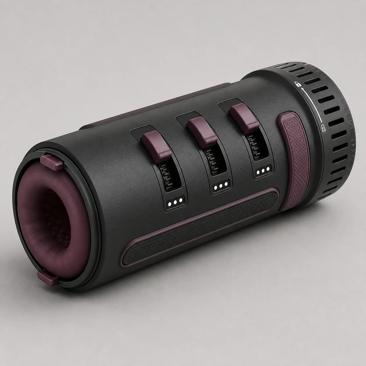
Three-Lever Zoned-Compression Manual Stroker with Depth Windows
A manual stroker concept with three independently adjustable compression levers, three depth windows, removable liner and one all-zone release bar.
49,99 $
200 in stock
Control three compression zones independently
This three-lever zoned-compression manual stroker concept places exactly three smoky-plum thumb levers in an axial row on one charcoal shell. Each lever aligns with its own three-dot depth window. A neutral removable liner, two release tabs, long grip rails, wide all-zone release bar, drainage slots and a ventilated twist-lock end cap complete the visible layout.

The image proposes a manual mechanism; it does not prove pressure, materials, fit, hygiene or production readiness.
Inventory shell liner and every compression channel
Require records for shell, liner, entry ring, tabs, zones Z1-Z3, levers L1-L3, cams, followers, pressure shoes, depth windows, detents, stops, release bar, linkage, grip rails, cap, lock, vents, drains, fasteners, pigments, lubricants and packaging.
Keep zone identities separate through teardown and testing.
Measure the neutral and compressed envelope
Record overall length and diameter, entry size, tunnel dimensions, liner wall, zone centers, lever travel, window indication, cap volume, grip span and mass at every permitted setting.
Repeat after compression cycles, cleaning, drying and storage.
Inspect the removable liner and entry interface
Map wall thickness, internal texture, entry radius, surface hardness, friction, deformation, rebound, attachment and tab strength. Check orientation marks and reinstall consistency.
Reject tears, tack, pigment transfer, hard exposure, trapped folds or a liner that migrates under approved loads.
Calibrate lever L1 and zone Z1
Measure actuation force, detent clarity, shoe travel, local deformation, pressure and release at all three indicated depths. Test alone and while Z2/Z3 remain neutral.
Record hysteresis and residual set rather than inferring pressure from lever position.
Calibrate lever L2 and zone Z2
Repeat the full travel, force, deformation and pressure map at the middle zone. Inspect whether its mechanism contacts neighboring followers or distorts the shell.
Reject cross-talk that changes another window or prevents independent release.
Calibrate lever L3 and zone Z3
Measure the end-zone mechanism beside the cap, including clearance to lock parts, vents and liner termination. Repeat with the cap installed and removed.
Reject cap interference, sharp follower edges or pressure that exceeds the accepted envelope.
Map combined three-zone pressure states
Test all approved L1-L3 combinations on instrumented compliant forms. Record local pressure, tunnel area, shell strain, liner shift and lever stability.
Publish a bounded matrix; do not describe maximum settings as universally suitable.
Validate the all-zone quick-release bar
Measure access, actuation force, travel, linkage response and pressure decay from every approved combination, including unequal loading and contamination challenges.
The release must not require moving any lever toward deeper compression first.
Audit detents windows and accidental movement
Compare each three-dot indication with measured shoe position from both directions. Challenge grip pressure, impact, twisting and cap operation in guarded fixtures.
Reject false seating, unreadable state, spontaneous advance or a lever that blocks the release bar.
Inspect cap ventilation and air response
Document cap lock angle, stop strength, vent area, airflow resistance and pressure change across zone combinations. Confirm whether the cap is storage, operational or both.
No suction claim is accepted without measured sealed-system evidence.
Screen pinch edges and liner damage paths
Probe lever slots, follower edges, window openings, release linkage, grip rails, entry rim, liner tabs, drains, cap lock and vents. Inspect during adjustment and disassembly.
Set clear limits for trapped material, sharpness, abrasion and loose components.
Validate cleaning drying and reassembly
Measure removal force, inversion limits if allowed, wash exposure, rinse clearance, drainage and drying time for liner, shell, shoes, drains, cap and vents.
Use only confirmed cleaners and reject persistent residue, odor, trapped moisture or unreliable orientation.
Cycle levers liner cap and release mechanism
Cycle L1-L3, detents, combined compression, release bar, liner removal, cap lock, cleaning, drying and storage. Remeasure travel, pressure, slip and shell strain at fixed intervals.
Retire for tears, shoe exposure, lever drift, window mismatch, delayed release, cap cracks, trapped residue or permanent liner set.
Build landed price from exact samples
An Alibaba simple-stroker page showed one manual product at USD 3.15-3.94 with MOQ one. It is a category benchmark only and does not confirm this three-lever mechanism or an approved supplier.
The procurement reference supports an EUR 49.99 planning price after provisional allowance for China-origin freight, exact samples, teardown, three-zone calibration, combined pressure maps, quick-release, cap airflow, hazard, cleaning and fatigue tests, protective packing and discreet fulfilment. Exact quote, MOQ, dimensions, materials, packed weight, freight, duty, tax, certification, payment terms and lead time remain pending.
Frequently asked questions
Can each zone use a different setting?
The concept proposes independent levers; cross-talk and safe combinations require testing.
What do the three dots indicate?
They are reference states whose actual shoe travel and pressure must be calibrated.
Does the wide bar release every zone?
The exact linkage and decay time require loaded sample tests.
Is the liner removable?
The visualization shows two tabs; removal force and reassembly reliability remain pending.
Does the cap create suction?
No suction performance is claimed without airflow and sealed-system measurements.
Which defects require retirement?
Tears, exposed shoes, lever drift, failed release, cap cracks, residue or permanent set.

Reviews
There are no reviews yet.