



Twin-Drum Four-Phase Palm Vibrator
August 14, 2026
Four-Band Compression-Grip Manual Stroker
August 14, 2026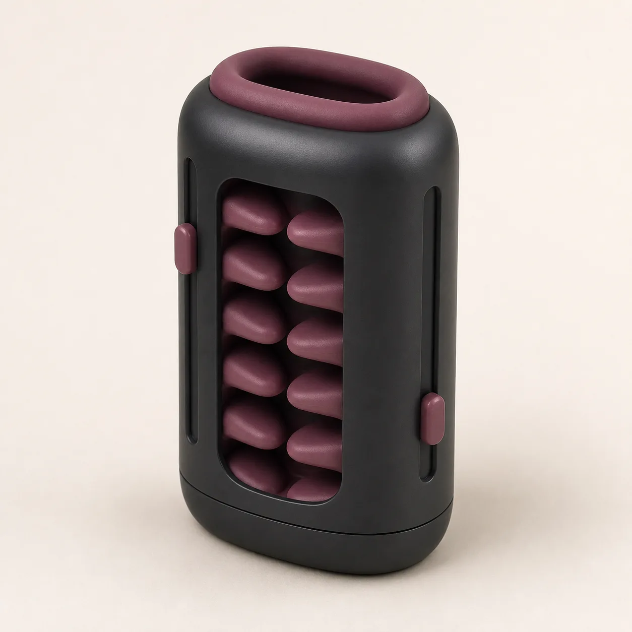
Dual-Rail Interleaved-Vane Manual Stroker with Split Tension Sliders
A compact manual stroker concept with two opposed slider rails and alternating rows of rounded internal vanes for separately testable pathway adjustment.
29,99 $
200 in stock
Two slider rails divide the internal adjustment task
This dual rail manual stroker concept places one recessed adjustment track on each side of a compact shell. A cutaway illustrates two alternating rows of rounded vanes so buyers can ask whether each slider changes one row, a shared support or only an external indicator.

The rendering does not prove separate tension circuits, vane travel, internal dimensions, material, waterproofing or cleaning method.
Establish what each slider actually moves
Request an exploded drawing and bill of materials covering shell, rim, sleeve, both vane rows, carriers, rails, sliders, detents, stops, seals, cap, pigments, lubricants and adhesives. Trace the mechanical path from each thumb slider to its linked components.
Mark any shared bridge or flexible wall that can make one setting alter the opposite row.
Measure the shell, pathway and two rail scales
Record external length, width and depth, opening dimensions, pathway depth, relaxed clearance, vane count, vane reach, row offset, rail travel, slider projection, cap thickness and total mass.
Measure left and right rails independently at their lowest, middle and highest stable positions; unlabeled travel is not evidence of equal adjustment.
Map the first rail without loading the second
Move the first slider through every stable position while the other remains at a documented reference point. Measure detent force, free play, linked vane displacement and any motion transferred to the opposite row.
Repeat after several full cycles to detect settling, creep or a slider that no longer holds position.
Map the second rail as a separate control
Repeat the same travel, force and displacement measurements for the opposite slider. Compare the two sides rather than assuming mirrored molding produces mirrored behavior.
Reject unexplained scraping, binding, jump movement or settings that cannot be reproduced.
Inspect how the vane rows interleave
Use borescope views and soft measurement fixtures to document vane spacing, overlap, tip radius, edge finish, carrier exposure and the closest approach between rows at all verified slider combinations.
No setting should create a hard scissor point, exposed support or inaccessible pocket.
Build a setting matrix instead of one intensity claim
Test low-low, low-high, high-low, middle-middle and maximum verified combinations. For each, log entry force on a standardized soft gauge, pathway compression, contact distribution, slider stability and removal force.
Publish only repeatable combinations within documented limits; two controls do not automatically create independent intensity.
Compare unloaded shape with compliant-load behavior
Photograph and measure vane position before contact, under several low approved fixture loads and after release. Note temporary folding, carrier rotation, delayed recovery and contact between the two rows.
Allow full recovery time before judging permanent deformation.
Check the oval rim and attached base cap
Inspect the rim for smooth radii, secure seating and a continuous transition into the internal pathway. Confirm the cap closes without trapping the sleeve, interfering with a rail or sealing moisture inside.
If the cap is removable in production, document retention force and whether it can be cleaned separately.
Keep both sliders stable during a manual stroke
Use a lubricated standardized mandrel and controlled test rig within supplier limits to measure sliding resistance at several settings. Observe whether grip pressure or repeated movement shifts either control.
Stop testing for slider drift, rail lift, hard contact, sudden resistance, torn surfaces or a displaced carrier.
Quantify resistance across the full travel
Record peak entry force, steady movement force, reversal force and force variation over the verified pathway. Compare readings at a fixed speed and lubrication quantity rather than relying on subjective labels.
High resistance is not automatically desirable and must remain within the confirmed product limits.
Cycle sliders, vanes and cap as one assembly
Run repeated slider adjustments, compliant-load strokes, cap opening and cleaning simulations. At planned checkpoints examine rails, detents, vane tips, carriers, rim, sleeve junctions and cap.
Track force drift, setting loss, surface whitening, cracking, tack changes, odor, swelling and residue accumulation.
Verify every contact and structural material
Obtain exact formulations for rim, internal sleeve, vanes, carriers, shell, sliders, rail liners, cap, pigments, lubricants and adhesives. Request restricted-substance and skin-contact evidence tied to the production revision.
Silicone, TPE, body-safe, medical-grade, hypoallergenic, phthalate-free and waterproof claims remain unconfirmed until exact-model documents and sample tests support them.
Open the pathway for complete cleaning and drying
Confirm whether the insert, cap or other service part can be removed without stressing the rail mechanism. Inspect behind vane rows, around carriers, inside rail recesses, under the rim and along cap seams.
Use only the verified cleaner and water exposure. Dry every hidden channel before closing the cap; boiling, dishwasher use, alcohol, bleach, powders and oils require explicit compatibility evidence.
Price the mechanism after teardown and freight checks
An Alibaba manual stroker listing currently shows USD 3.15-3.94 with an MOQ of one piece. It is a category benchmark only and does not confirm this dual-rail, interleaved-vane mechanism or an approved supplier.
The procurement reference supports an EUR 29.99 planning price after allowing for China-origin freight, exact-part inventory, two-rail travel measurement, setting-matrix tests, vane-clearance inspection, compliant-load force mapping, slider retention, cycle life, material documentation, cleaning validation, protective packing and discreet fulfillment. Exact quotation, packed dimensions, weight, freight, duty, tax, insurance, payment fees and delivery terms remain pending.
Frequently asked questions
Do the two sliders control separate vane rows?
That is the intended evaluation concept, but the production linkage and any shared carrier must be confirmed.
Can the sliders be set at different heights?
Only stable positions documented by the supplier and sample tests should be used; visible rail travel alone is not an approved range.
Are more overlap and more resistance the same thing?
No. Overlap, pathway compression and measured movement force are related but distinct values.
Does the cutaway window appear on the final product?
The image is an explanatory visualization; production shell construction and inspection access remain pending.
Can the insert be removed for washing?
That must be confirmed from the exact assembly and instructions before any cleaning claim is published.
Which faults require retirement?
A torn rim, split vane, exposed carrier, drifting slider, cracked rail, loose cap, permanent distortion, tack change, trapped residue or any surface that cannot be cleaned and dried.

Reviews
There are no reviews yet.