


Dual-Chamber Selector-Manifold Rechargeable Vacuum Pump Kit
August 14, 2026
Twin-Roller Full-Hinge Manual Stroker with Removable Wave Liner
August 14, 2026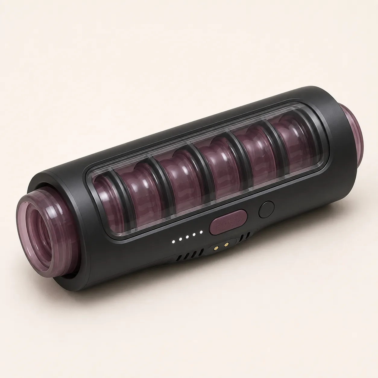
Five-Diaphragm Sequential-Compression Automatic Stroker
An open-through automatic stroker concept with five visible annular diaphragm stations, sequential compression controls, immediate stop and charging contacts.
92,99 $
200 in stock
Sequence five diaphragm stations around one liner
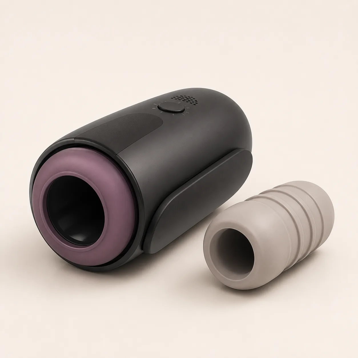
This five-diaphragm sequential-compression automatic stroker concept places one removable smoky-plum through-liner inside a charcoal open-ended shell. A transparent inspection window exposes exactly five annular diaphragm stations separated by dark ribs, while one slider and five white indicators propose selectable compression timing.

The image defines an evaluation architecture; it does not prove pneumatic action, compression range, materials, battery or production status.
Identify every fluid mechanical and electrical path
Label liner L0; stations D1-D5; divider ribs R1-R5; window W0; end retainers E1-E2; sequence slider S0; indicators I1-I5; stop button B0; vents V1-V5; contacts J1-J2; pump or actuators, valves, manifold, controller, cell, seals and fasteners.
Require an exact-sample drawing, hose and valve map, firmware identity and bill of materials.
Measure the open-through liner before operation
Record relaxed bore, wall thickness, working length, flange geometry, hardness, friction, mass and dimensional variation along L0. Measure retention at both ends and inspect the window side for uneven support.
Reject tears, tack, exposed hard edges, thin zones, flange lift or uncontrolled liner migration.
Calibrate diaphragm D1 through D5
Measure each station’s axial position, active length, relaxed aperture, maximum safe displacement, rise time, hold behavior, release time and repeat-position error. Use instrumented compliant cylinders rather than human trials.
Five visible rings are not five independent channels until pressure and timing data identify their actual behavior.
Decode the proposed five-stage sequence control
Map S0 travel, I1-I5 and B0 actions to direction, active station, overlap, speed, pause and immediate stop. Capture valve or actuator commands together with station pressure and aperture.
Separate a genuine traveling compression wave from simultaneous pulsing or indicator animation.
Build axial pressure and timing maps
Place synchronized pressure sensors at the center of D1-D5 and between adjacent stations. Record onset, peak, duration, overlap and decay for every confirmed program and intensity.
Plot wave direction and continuity so unequal stations or dead zones are visible.
Repeat mapping across standardized fixture sizes
Use bounded compliant fixtures spanning the supported range. Log liner stretch, station pressure, sequence speed, current, sound, temperature and end-retainer movement at each size.
Do not convert fixture results into universal-fit statements.
Inspect window dividers and moving clearances
Measure W0 thickness, clarity, attachment and distance from D1-D5 throughout operation. Probe R1-R5, liner gaps, end retainers and window edges for pinch, snag, abrasion and trapped residue.
Reject diaphragm contact with the window, loose ribs, sharp transitions, fogging or visible fastener movement.
Verify stop vent and pressure-loss behavior
Measure B0 access and time from actuation to drive stop and pressure release at all stations. Challenge blocked vents, stuck-valve simulations, power loss, low voltage and one-station restraint in guarded fixtures.
The system must fail toward a documented low-energy state without unexpected restart.
Trace airflow heat and acoustic sources
Map inlet and outlet paths through V1-V5 and any internal manifold. Measure A-weighted sound and temperatures at each station, pump or motor, valves, controller, cell, vents, window and contacts.
Distinguish normal switching noise from leaks, valve chatter, diaphragm impact, bearing wear and obstructed flow.
Validate controls charging and battery protection
Document startup, sequence selection, intensity, pause, immediate stop, travel lock and low-battery response. Confirm J1-J2 polarity, charge time, operating time, cutoff behavior, standby drain and contact temperature.
Exact battery chemistry, capacity, cable, input limits and transport documents remain pending supplier evidence.
Design liner removal cleaning and drying tests
Time liner removal and refitting without tools, then challenge flanges, bore, station interfaces, divider gaps, window edges, vents, buttons and contacts with visible test soil. Record residue, drying time, swelling, odor and corrosion.
No waterproof, immersion or dishwasher claim is made without exact-model evidence.
Confirm materials and production workmanship
Request declarations for the liner, diaphragms, shell, window, ribs, seals, valves, tubing, pigments, adhesives and lubricants. Check odor, color transfer, surface finish, coating adhesion and batch traceability.
No silicone, body-safe, hypoallergenic or certification claim is accepted while traceable documents remain pending.
Cycle sequences faults and cleaning exposure
Cycle every confirmed wave direction and speed across supported fixtures, then repeat liner removal, cleaning, drying, charging and storage. Remeasure station pressure, timing, window clearance, sound, heat, valve leakage and retention.
Retire samples for tears, diaphragm drift, valve faults, pressure retention, window damage, abnormal heat, fluid entry, charging faults or cell swelling.
Build landed price after five-station validation
An Alibaba automatic-stroker category page showed one motorized example at USD 30.00 to 32.00 with a one-piece minimum. It is a broad benchmark only and does not identify this five-diaphragm system or an approved supplier.
The public procurement benchmark supports an EUR 92.99 planning price after provisional allowance for China-origin freight, exact samples, liner and station metrology, pressure and timing maps, valves, airflow, stop and vent tests, sound, heat, charging, cleaning, fault and fatigue work, protective packing and discreet fulfilment. Exact supplier, quote, MOQ, dimensions, materials, battery, packed weight, freight, duty, tax, certification, payment terms and lead time remain pending.
Frequently asked questions
Are all five diaphragm stations independently driven?
Independent actuation requires pressure, command and timing evidence from the exact sample.
Does compression travel in both directions?
Wave direction and overlap must be verified for each confirmed program.
Can the through-liner be removed?
The concept proposes a removable liner; retention, removal force and refitting accuracy require testing.
What happens after the stop button is pressed?
Drive-stop and pressure-release time must be measured at all five stations.
Is the unit waterproof?
No ingress claim is made for the window, seams, vents, controls or charging contacts.
Which faults require retirement?
Tears, pressure retention, valve faults, window damage, heat, fluid entry, charging faults or cell swelling.
Reviews
There are no reviews yet.