


Mock-Neck Long-Sleeve Diamond-Net Bodystocking with Twin Chevron Waist Panels
August 14, 2026
Twin-Module Three-Stop Wrist-to-Thigh Restraints with Guarded Bridge Sleeves
August 14, 2026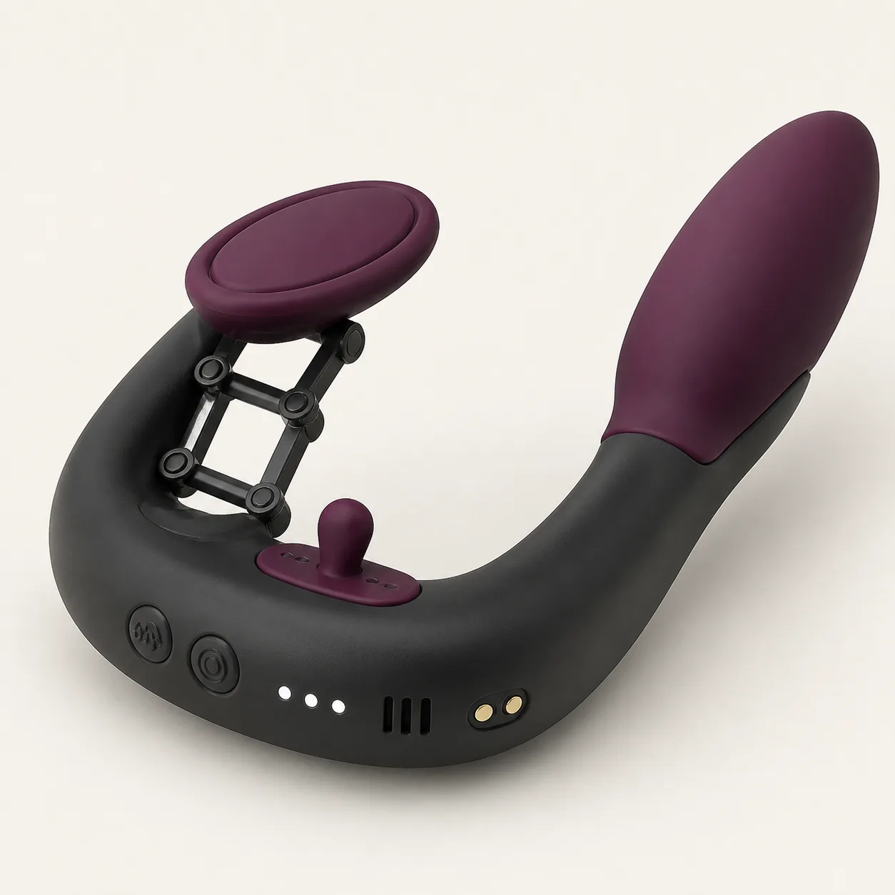
Three-Stop Parallel-Lift Couples Vibrator with Four-Bar Contact Pod
An open U-shaped couples vibrator concept with two unequal pods and a four-bar mechanism proposed to lift one contact pad through three positions.
54,99 $
200 in stock
Raise one contact pod through a four-bar lift
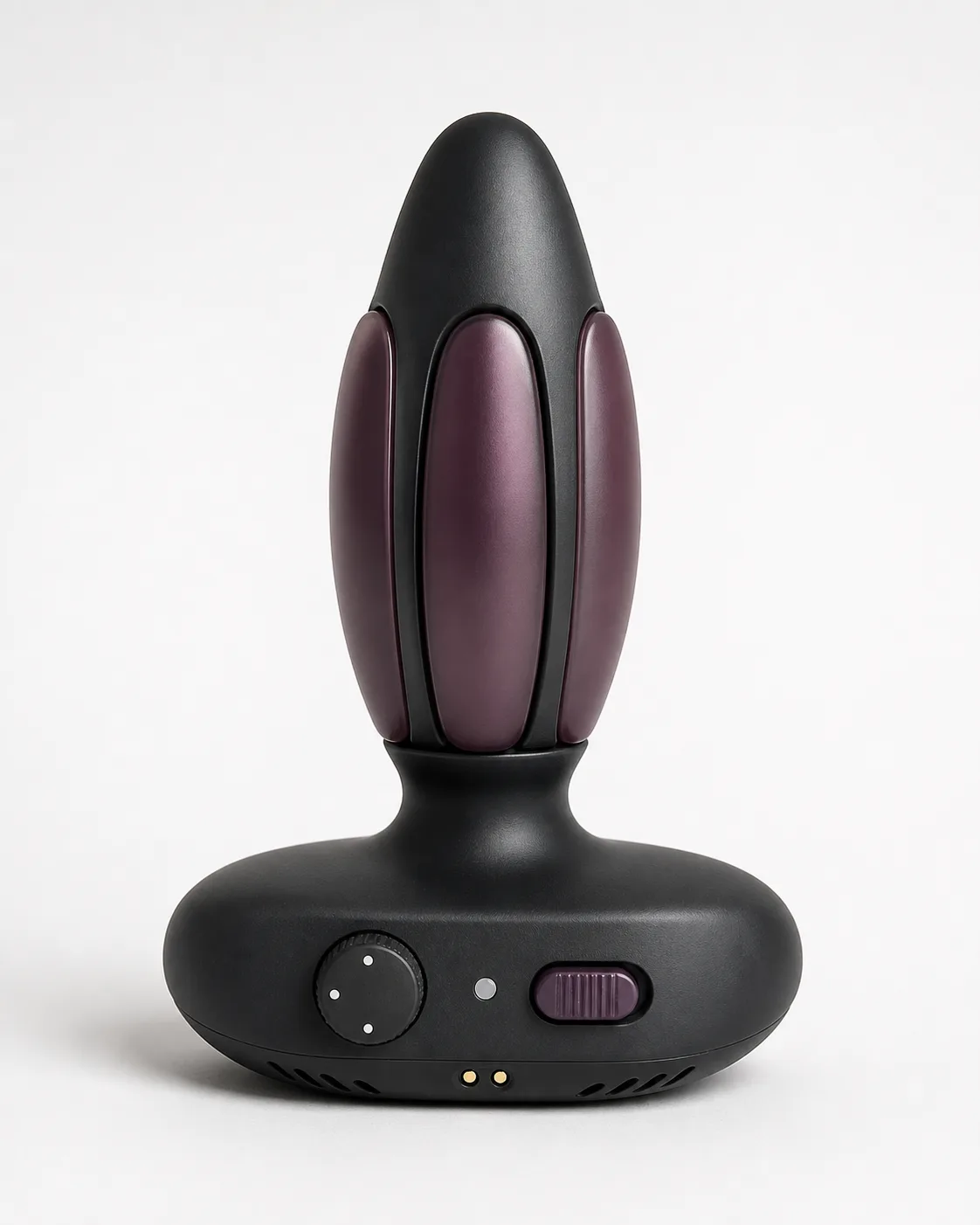
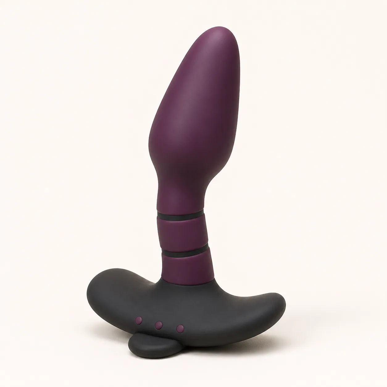
This parallel lift couples vibrator concept places a shallow oval contact pod on a compact four-bar mechanism inside an open U-shaped bridge. A guarded three-stop lever is proposed to change pod height while the opposite longer pod remains fixed to the other arm.

The image does not prove lift travel, pod parallelism, fit, motor count, programs, retention, ingress protection, runtime, materials or supplier approval.
Inventory every linkage and electrical part
Request an exploded drawing and bill of materials for both pod faces, pod cores, U bridge, four linkage arms, pivot caps, pins, bushings, lift carriage, lever, detents, stops, locks, motors, counterweights, sensors, controller, buttons, indicators, vent, cell, contacts, conductors, seals, pigments, lubricants and adhesives.
Identify load paths from the raised pod to the bridge and from the lever to each linkage arm.
Measure the baseline U geometry
At the verified lowest lift stop, record overall length, bridge gap, arm thickness, curvature, small-pod dimensions, long-pod dimensions, pod separation, pivot spacing, lever projection, vent area, contact spacing, mass and center of gravity.
Repeat at each stop under no load and standardized preload to capture bridge opening and mechanism compliance.
Calibrate the three-stop lift lever
Measure lever travel, actuation force, detent force, engagement depth, backlash and accidental movement resistance at every position. Approach each stop from both directions and test with dry and damp grips.
Reject a lever state that appears seated while the lift carriage remains between defined positions.
Solve the four-bar kinematics
Track coordinates of every pivot, linkage angle, carriage height, lateral shift and mechanical advantage throughout the permitted lift path. Compare the left and right arms for play and phase.
Inspect for over-center behavior, a crossed linkage, pin rotation in the housing or a hard stop reached by only one side.
Measure contact-pod parallelism
Record small-pod pitch, roll, yaw and surface plane relative to the local bridge reference at each lift stop under unloaded and compliant-loaded conditions. Map error across the full pad.
A four-bar shape suggests parallel motion but does not guarantee it after molding tolerance, bushing wear or asymmetric load.
Map pressure at all lift positions
Use an instrumented compliant fixture to record contact area, peak pressure, edge pressure, shear and rocking for the raised pod at each stop. Repeat with slight lateral offsets.
Define conservative limits from the highest local value and link stress, not from lever position or average surface pressure.
Characterize the longer opposite pod
Measure its profile, surface compression, bending stiffness, fixed-angle tolerance and pressure distribution separately. Then test how bridge flex and raised-pod load change its position.
Do not assume the fixed pod remains static when the U bridge opens, twists or carries unequal motor loads.
Test vibration channels independently
Confirm the actual motor count and assignment. Measure three-axis acceleration, dominant frequency, harmonics, rise time, decay, sound and current at each pod for every verified program and lift stop.
Document cross-coupling through the bridge and any phase or amplitude change as the linkage height changes.
Measure fit retention without relying on tension
Use standardized compliant paired fixtures to record bridge opening force, pod separation, rotation resistance, migration and stable orientation at each lift stop. Apply controlled axial and torsional disturbances.
Stop if the lift collapses, lever moves, bridge takes permanent set or either pod develops an edge pressure spike.
Map every moving pinch gap
Use feeler gauges and articulated fixtures around all pivot caps, crossing paths, arm-to-carriage gaps, lever slot, pod underside and bridge recess throughout lift and loading.
Guards must block skin access without adding sharp edges, hidden debris pockets or a surface that catches fabric.
Document controls and battery behavior
Record startup hold, channel selection, program order, increase and decrease behavior, pause, immediate stop, memory, lockout and low-charge indication. Confirm mechanical lift changes cannot restart or alter a stopped program.
Verify cell chemistry, capacity, protection, input, contact polarity, charge time, runtime method, storage guidance and transport paperwork.
Test heat, ingress and fault response
Log temperature at both pods, all pivots, lever, bridge, controls, vent, contacts, motor zones and cell across lift settings and representative loads. Ingress claims require exact evidence for every seam and moving joint.
Use protected fixtures for a jammed linkage, one seized pivot, stalled motor, obstructed vent, drop event and low-voltage cutoff. Do not re-energize a hot, cracked or rattling sample.
Cycle lifting, vibration and cleaning together
Run repeated lever traversal, detent seating, fixture loading, independent and combined vibration, immediate stop, charging, cleaning, drying and storage cycles. At checkpoints repeat kinematics, parallelism, pressure, pivot play, output, sound and heat tests.
Clean both pod faces, link arms, pivot caps, carriage gaps, lever track, controls, vent and contacts by the verified method; measure drying before cycling or charging.
Price the linkage after loaded testing
An Alibaba couples-vibrator listing currently shows a dual-head category example at USD 9.59-9.99 with MOQ one thousand. It is a category benchmark only and does not confirm this four-bar lift, three-stop lever, paired pods or production terms.
The procurement reference supports an EUR 54.99 planning price after allowing for China-origin freight, exact-model sourcing, teardown, U-geometry metrology, lever calibration, four-bar kinematic analysis, loaded parallelism, pressure maps, dual-pod output, fit retention, pinch inspection, battery, thermal and fault review, cycle life, material evidence, cleaning validation, protective packing and discreet fulfillment. Exact quotation, MOQ, packed size, weight, freight, duty, tax, insurance, payment fees and delivery terms remain pending.
Frequently asked questions
Does the raised pod stay perfectly parallel?
No. Parallelism must be measured across load, temperature, manufacturing tolerance and pivot wear.
Are there three verified heights?
No. Visible stops require measured carriage height, detent engagement and repeatability.
Does each pod have its own motor?
Motor count, assignment and cross-coupling remain pending teardown and output testing.
Can the lever move while powered?
The approved adjustment sequence and any interlock require exact instructions and fault review.
Can the linkage be immersed?
No ingress claim is made; pivot and carriage gaps require the documented cleaning method.
Which faults require retirement?
A loose pin, seized pivot, collapsed lift, false detent, cracked arm, torn pod, opening seam, exposed conductor, swollen cell or abnormal heat.
Reviews
There are no reviews yet.